| |
 Introduction, and survey design Introduction, and survey design
Seismic refraction surveys produce results
that describe the subsurface structure beneath the survey line as a sequence
of dipping layers. Depending on the complexity of field and processing methods,
the seismic velocity in each layer may be assumed to be constant, and the layer
interfaces may be either planar or more complicated. For engineering work data are nearly always
gathered along lines, and results are interpreted assuming the earth is essentially
two dimensional.
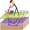
Survey design considerations include location of lines, the
type and spacing of geophones and shot points, and the type of energy source.
For this project, one north-south (located along 12E) and one east-west line (along 54N) were surveyed, but
only the north-south line produced usable results. Geophones
were placed at 2m intervals in spreads of 12 geophones, so four spreads were
required to cover each 100m long line. Two forward shots and two reverse shots
were recorded into each of these four spreads of geophones. Shot offsets at both ends of each spread were 2m and 15m. A
simple 10 pound hammer swung onto a metal plate provided a sufficient energy
source for this small survey.
Effects of Pavement
There were three complications caused by the 45cm thick pavement
that covered the site.
- Geophones mounted on heavy base plates were required because
spiked geophones could not be forced into the pavement. As a result, many
of the records were contaminated with ringing or rattling.
- The relatively high velocity of pavement caused concern
because velocities must increase with depth if layer interfaces are to be visible on a refraction survey. In spite of that,
useful direct and refracted signals were detected, therefore pavement appears
to have been thin enough to be essentially un-detectable.
- Direct arrivals of seismic energy through the fill layer
were not consistently recorded, probably because of the pavement. However,
enough direct arrivals were obtained to estimate fill velocity at a few locations. Applying these few estimates of the fill velocity at all locations may, of course, cause some errors in depth estimates because fill materials are known to be variable across the site.
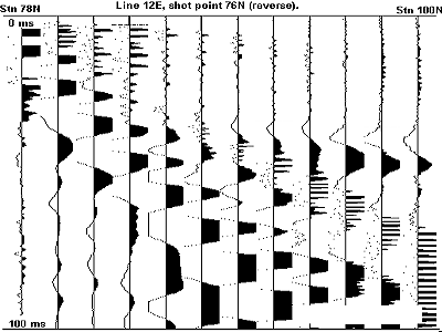 Raw
data Raw
data
The figure to the right with 12 seismic traces is an example of records from
one shot. First arrivals are evident on traces 5 through 12, but they are hidden by ground roll and high frequency ringing on traces 1 through 4. Further complexities
affecting seismic refraction interpretation included the uncertain depth of the
water table, and the presence of a thin layer of marine silts between fill and
till.
Interpreted results
The interpretation figure below shows the result of interpretation
using a simple intercept time solution. Vertical axis limits are labelled on the left
side of each of the three panels.
- Top panel: this shows first arrival time picks interpreted
from raw recorded traces.
- Middle panel: estimates of layer velocities are shown. The
top layer's velocity of 577m/s was estimated from the few direct arrivals recorded.
The second layer's velocity was interpreted to be between 1300m/s and 1400m/s
for most of the section, and 1770m/s under the southern spread (left
end of the figure).
For this southern spread, several attempts at picking first
arrivals, and assigning correct layers for the first arrivals, produced refractor
velocities between 1300m/s and 2000m/s. The layer of silt that apparently
exists at some locations between fill and till is thin, so it is not certain
whether velocities interpreted for the refractor represent silt or till velocities.
However, velocities are compatible with those expected for a dense glacial
till, and layers that are much thinner than the signal wavelength tend to
be essentially invisible (as mentioned above with respect to the pavement
layer), especially if the thin layer has a velocity between those of adjacent
materials.
- Bottom panel: this shows estimates of depths to geological
interfaces. These depths are consistent with expectations based upon boreholes
and trenching.
South 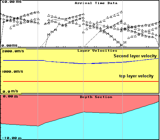 North North
|
|