This page: | Introduction | Forward modelling | borehole | Inversion | Depth weighting | Wavelet compression | Regularization | Example |
1.1 Introduction
This manual presents theoretical background, numerical examples, and explanation for implementing the program library MAG3D. This suite of algorithms, developed at the UBC- Geophysical Inversion Facility, is needed to invert magnetic responses over a three-dimensional susceptibility distribution. The manual is designed so that a geophysicist who is familiar with the magnetic experiment, but who is not necessarily versed in the details of inverse theory, can use the codes and invert his or her data.
A magnetic experiment involves measuring the anomalous magnetic field produced by magnetically susceptible materials beneath the surface, which have been magnetized by the earth's main magnetic field . The material with susceptibility  is magnetized when the is magnetized when the
earth's main field with flux intensity  impinges upon the subsurface formation. The magnetized material gives rise to a magnetic field, impinges upon the subsurface formation. The magnetized material gives rise to a magnetic field,  , which is superimposed on the inducing field to produce a total, or resultant, field. By measuring the resultant field and removing the inducing field from the measurements through numerical processing, one obtains the distribution of the anomalous field due to the susceptible material. Very often, the susceptible materials underground possess a certain amount of natural remanent magnetization. In this program library, however, we make the assumption that no remanent magnetization is present and restrict our attention to induced magnetization. , which is superimposed on the inducing field to produce a total, or resultant, field. By measuring the resultant field and removing the inducing field from the measurements through numerical processing, one obtains the distribution of the anomalous field due to the susceptible material. Very often, the susceptible materials underground possess a certain amount of natural remanent magnetization. In this program library, however, we make the assumption that no remanent magnetization is present and restrict our attention to induced magnetization.
The data from a typical magnetic survey is a set of magnetic field measurements acquired over a 2D grid above the surface or along a number of boreholes within the volume of interest. These data are first processed to yield an estimate of the anomalous field due to the susceptible material in the area. The goal of the magnetic inversion is to obtain, from the extracted anomaly data, quantitative information about the distribution of the magnetic susceptibility in the ground. Thus it is assumed that the input data to the inversion program is the extracted residual anomaly and the programs in the library are developed accordingly.
1.2 Forward Modelling
General Formulation
For a given inducing field , the magnetization  depends upon the susceptibility through a differential equation. However, to the first order approximation when the actual susceptibility is very small, as is most often the case with material encountered in mineral explorations, the magnetization is proportional to the susceptibility and is given by the product of susceptibility with inducing magnetic field depends upon the susceptibility through a differential equation. However, to the first order approximation when the actual susceptibility is very small, as is most often the case with material encountered in mineral explorations, the magnetization is proportional to the susceptibility and is given by the product of susceptibility with inducing magnetic field  , ,
 (1) (1)
where  and and  is the free space magnetic permeability. This essentially ignores the self-demagnetization effect by which the secondary field reduces the total inducing field within the susceptible region and results in a weaker magnetization than that given by eq. (1). is the free space magnetic permeability. This essentially ignores the self-demagnetization effect by which the secondary field reduces the total inducing field within the susceptible region and results in a weaker magnetization than that given by eq. (1).
The anomalous field produced by the distribution of magnetization is given by the following integral equation with a dyadic Green's function,
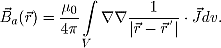 (2) (2)
where  is the position of the observation point. V represents the volume of magnetization. The above equation is valid for observation locations above the earth's surface. It is also valid in the boreholes provided we assume that the magnetic permeability is . is the position of the observation point. V represents the volume of magnetization. The above equation is valid for observation locations above the earth's surface. It is also valid in the boreholes provided we assume that the magnetic permeability is .
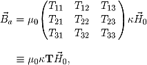
When the susceptibility is constant within a volume of source region, the above equation can be written in matrix form as
 (3) (3)
where  is given by is given by
 (4) (4)
where x1, x2, and x3 represent x, y, and z, respectively. The expressions of for a cuboidal source volume can be found in Bhattacharyya (1964) and Sharma (1966). (Here we assume that the effect of borehole cavity can be neglected.) Since T is symmetric and its trace is equal to -1 when the observation is inside the cell and is 0 when the observation is outside the cell, only five independent elements need to be calculated.
Once T is formed, the magnetic anomaly and its projection onto any direction of measurement is easily obtained by the inner product with the directional vector. The projection of the field onto different directions yields different anomalies commonly obtained in the magnetic survey. For instance, the vertical anomaly is simply  , the vertical component of , whereas the total field anomaly is, to first order, the projection of onto the direction of the inducing fiels . , the vertical component of , whereas the total field anomaly is, to first order, the projection of onto the direction of the inducing fiels .
Borehole Data
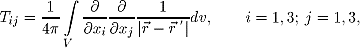
In a borehole experiment, the three components are measured in the directions of local coordinate axes (x1, y1, z1) defined according to the borehole orientation. Assuming that the borehole dip  is measured downward from the horizontal surface and azimuth is measured downward from the horizontal surface and azimuth  is measured eastward from the north, a commonly used convention has the z1–axis pointing downward along borehole, x1–axis pointing perpendicular to the borehole in the direction of the azimuth. The y1–axis completes the right-handed coordinate system and is 90o clockwise from the azimuth and perpendicular to the borehole. Based upon the above definition the rotation matrix that transforms three components of a vector in the global coordinate system to the components in the local coordinates is given by is measured eastward from the north, a commonly used convention has the z1–axis pointing downward along borehole, x1–axis pointing perpendicular to the borehole in the direction of the azimuth. The y1–axis completes the right-handed coordinate system and is 90o clockwise from the azimuth and perpendicular to the borehole. Based upon the above definition the rotation matrix that transforms three components of a vector in the global coordinate system to the components in the local coordinates is given by
 (5) (5)
If a vector is define in local coordinates as  , and in global coordinates as , and in global coordinates as  , then the following two relations hold; , then the following two relations hold;
 (6) (6)
The rotation matrix R therefore allows measured components in local coordinates to be rotated into global coordinates, or the components of the regional field to be rotated into local coordinates for use in regional removal.
Numerical Implementation
We divide the region of interest into a set of 3D cuboidal cells by using a 3D orthogonal mesh and assume a constant susceptibility within each cell. By eq.(1), we have an uniform magnetization within each cell and its field anomaly can be calculated using eqs.(3) and (6). The actual anomaly that would be measured at an observation point is the sum of fields produced by all cells having a non-zero susceptibility value. The calculation involves the evaluation of eq. (3) in a 3D rectangular domain defined by each cell. The program that performs this calculation is MAGFOR3D. As input parameters, the coordinates of the observation points and the inclination and declination of the anomaly direction must be specifie for each datum. For generality, each component in a multi-component data set is specified as a separate datum with its own location and direction of projection.
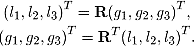
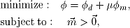
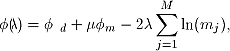
As an illustration of the forward modelling program, we calculate the total field anomaly above the surface and three-component anomaly in boreholes produced by a synthetic model. The model consists of two vertical prisms buried at different depths. Figure 1 displays one cross-section and one plan-section of the model. The inducing field has inclination I=65o and declination D=25o. The surface anomaly is calculated at an interval of 25m over seven east-west lines spaced 100 m apart. The borehole data are calculated in three vertical holes at an interval of 25m. Figure 2 shows the contour map of the surface data and the depth profiles of the borehole data.
|
Figure 1.
Two sections of a susceptibility model consisting of two prisms buried in a nonsusceptible background. The collar positions of three vertical boreholes are indicated on the plan-section. |
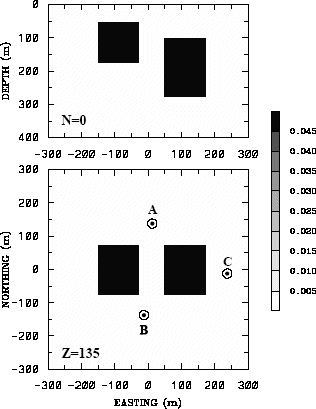 |
Figure 2. The panel on the left is the total field anomaly on the surface produced by the model in Figure 1 under an inducing field with declination and inclination noted above. The panels on the right are the three-component anomalies in three vertical boreholes. Different components are identifie by the labels beside the curves.
|
1.3 Inversion Methodology for Ver 3.1.
(Notes regarding modifications for Ver 4.0 are provided below). Let the set of extracted anomaly data be  and the susceptibility of cells in the model be and the susceptibility of cells in the model be 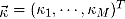 . The two are related by the sensitivity matrix . The two are related by the sensitivity matrix
 (7) (7)
The matrix has elements gij which quantify the contribution to the ith datum due to a unit susceptibility in the jth cell (see Section 1.2). The program MAGSEN3D performs the calculation of the sensitivity matrix , which is to be used by the subsequent inversion. The sensitivity matrix gives the forward mapping from a model to data during the entire inverse process. We will discuss its efficient representation via the wavelet transform in a separate section.
The inverse problem is formulated as an optimization problem where an objective function of the model is minimized subject to the constraints in eq.7. For magnetic inversion the first question that arises concerns definition of the "model". We choose  as the model since the anomalous field is directly proportional to the susceptibility. This is the choice for the inversion program MAGINV3D. For generality, we introduce the generic symbol m for the model element. Having define a "model" we next construct an objective function which, when minimized, produces a model that is geophysically interpretable. The details of the objective function are problem dependent but generally we need the flexibility to be close to a reference model m0 and also require that the model be relatively smooth in three spatial directions. Here we adopt a right handed Cartesian coordinate system with positive north and positive down. Let the model objective function be as the model since the anomalous field is directly proportional to the susceptibility. This is the choice for the inversion program MAGINV3D. For generality, we introduce the generic symbol m for the model element. Having define a "model" we next construct an objective function which, when minimized, produces a model that is geophysically interpretable. The details of the objective function are problem dependent but generally we need the flexibility to be close to a reference model m0 and also require that the model be relatively smooth in three spatial directions. Here we adopt a right handed Cartesian coordinate system with positive north and positive down. Let the model objective function be
 (8) (8)
where the functions ws , wx, wy and wz are spatially dependent while  s, x, y, and z are coefficient which affect the relative importance of different components in the objective function. Here the function s, x, y, and z are coefficient which affect the relative importance of different components in the objective function. Here the function  is a generalized depth weighting function. The purpose of this function is to counteract the geometrical decay of the sensitivity with the distance from the observation location so that the recovered susceptibility is not concentrated near the observation locations. The details of the depth weighting function will be discussed in the next section. is a generalized depth weighting function. The purpose of this function is to counteract the geometrical decay of the sensitivity with the distance from the observation location so that the recovered susceptibility is not concentrated near the observation locations. The details of the depth weighting function will be discussed in the next section.
The values s, X, Y, and Z are coefficients which affect the relative importance of the different components of the objective function. The greater the ratio X/s and so on, the smoother the recovered model is in that axis direction. A length scale of smoothness can be defined for each direction as  , ,  , ,  ; and specifying greater values for the length scales will produce smoother models. ; and specifying greater values for the length scales will produce smoother models.
The objective function in eq. (8) has the flexibility to construct many different models. The reference model m0 may be a general background model that is estimated from previous investigations or it could be the zero model. The reference model would generally be included in the first component of the objective function but it can be removed if desired from the remaining terms; often we are more confident in specifying the value of the model at a particular point than in supplying an estimate of the gradient. The relative closeness of the final model to the reference model at any location is controlled by the function ws. For example, if the interpreter has high confidenc in the reference model at a particular region, he can specify ws to have increased amplitude there compared to other regions of the model. The weighting functions wx, wy, and wz can be designed to enhance or attenuate structures in various regions in the model domain. If geology suggests a rapid transition zone in the model, then a decreased weighting for flatness can be put there and the constructed model will exhibit higher gradients provided that this feature does not contradict the data.
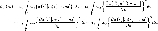
To perform a numerical solution, we discretize the model objective function in eq. (8) using a finite difference approximation on the mesh defining the susceptibility model. This yields
 (9) (9)
where m and m0 are M-length vectors. The individual matrices Ws , Wx, Wy and Wz are straight- forwardly calculated once the model mesh and the weighting functions and ws , wx, wy, wz are defined The cumulative matrix  is then formed. is then formed.
The next step in setting up the inversion is to define a misfit measure. Here we use the 2–norm measure
 (10) (10)
For the work here we assume that the contaminating noise on the data is independent and Gaussian with zero mean. Specifying Wd to be a diagonal matrix whose ith element is 1/ , where is the standard deviation of the ith datum, makes , where is the standard deviation of the ith datum, makes  d a chi-squared variable distributed with N degrees of freedom. Accordingly d a chi-squared variable distributed with N degrees of freedom. Accordingly  provides a target misfit for the inversion. provides a target misfit for the inversion.
The inverse problem is solved by finding a model m which minimizes m and misfits the data by a pre-determined amount. Since the susceptibility is positive by definition we also need to impose the constraint that all model elements be positive. Thus the solution is obtained by the following minimization problem,
 (11) (11)
where  is a tradeoff parameter that controls the relative importance of the model norm and data misfit. When the standard deviations of data errors are known, the acceptable misfit is given by the expected value is a tradeoff parameter that controls the relative importance of the model norm and data misfit. When the standard deviations of data errors are known, the acceptable misfit is given by the expected value  and we will search for the value of that produces the expected misfit. Otherwise, an estimated value of will be prescribed. The details of various aspects of choosing a tradeoff parameter will be discussed in a following section. and we will search for the value of that produces the expected misfit. Otherwise, an estimated value of will be prescribed. The details of various aspects of choosing a tradeoff parameter will be discussed in a following section.
We use a primal logarithmic barrier method with the conjugate gradient technique as the central solver. In the logarithmic barrier method, the positivity constraint is implemented as a logarithmic barrier term. The new objective function is given by
 (12) (12)
where  is the barrier parameter, and the tradeoff parameter is fixed during the minimization. As the name suggests, the logarithmic barrier term forms a barrier along the boundary of the domain of feasible solutions, and prevents the minimization from crossing over to the infeasible region. The method solves a sequence of nonlinear minimizations with decreasing and, as approaches zero, the sequence of solutions approach the solution of eq. (11). is the barrier parameter, and the tradeoff parameter is fixed during the minimization. As the name suggests, the logarithmic barrier term forms a barrier along the boundary of the domain of feasible solutions, and prevents the minimization from crossing over to the infeasible region. The method solves a sequence of nonlinear minimizations with decreasing and, as approaches zero, the sequence of solutions approach the solution of eq. (11).
This methodology provides a basic framework for solving 3D magnetic inversion with arbitrary observation locations. The basic components are the forward modelling, a model objective function that incorporates a "depth" weighting, a data misfit function, a tradeoff parameter that ultimately determines how well the data will be fit, and the logarithmic barrier method to obtain the solution with positivity. Without getting into the algorithmic details, we discuss three of these basic components in the next sections, namely, the depth weighting, efficient forward mapping, and the choice of the tradeoff parameter. An understanding of these components is necessary for the user to have a global view of the algorithm and to use the program library correctly.
Notes regarding MAG3D Ver.4.0.
In MAG3D versions 3.1 and earlier the condition of positivity in the model was imposed by implementing a modification to the model objective function. In Version 4.0 a more general condition can be imposed such that lower and upper bounds on values of susceptibility in the model can be defined. This is useful because often there are well-defined bounds on the susceptibility contrast based on direct sampling or other geological information.
The procedure for implementing upper and lower bounds on model values is the same as that used in GRAV3D Version 2.0 and later. In MAG3D the positivity constraint is no longer necessary if upper and lower bounds are defined. However, if the user chooses to not define upper and lower bounds, the program employs default bounds for susceptibilities in every cell of 1.0 and 0.0 respectively (S.I. units). While it is true that some rocks have susceptible greater than 1.0, MAG3D Version 4.0 still assumes small susceptibilities, as this code has done since the original version. When there are very high susceptibilities, the relation between incident and induced magnetization is no longer linear, and the problem becomes more complicated. Inverting data in the presence of very high susceptibilities is still a topic of research, and MAG3D Version 4.0 does not allow for high susceptibilities in the solution.
As a result of implementing upper and lower bounds, equations (11) and (12) above are different for MAG3D Version 4.0. Instead of imposing positivity, the solution is obtained by the following minimization problem, which replaces equation (11):
 (11b) (11b)
where min and max are vectors containing the lower and upper bounds on the model values, and is the vector containing model values.
As before, we use the primal logarithmic barrier method with the conjugate gradient technique as the central solver. In the logarithmic barrier method, the bounds constraints are implemented as a logarithmic barrier term. The new objective function is given by
 (12b) (12b)
where is the barrier parameter, and the regularization parameter is fixed during the minimization. As the name suggests, the logarithmic barrier term forms a barrier along the boundary of the feasible domain and prevents the minimization from crossing over to the infeasible region. The method solves a sequence of nonlinear minimizations with decreasing and, as approaches zero, the sequence of solutions approach the solution of eq (11b).
1.4 Depth Weighting
"Depth" weighting for surface or airborne data
It is a well known fact that static magnetic data have no inherent depth resolution. A numerical consequence of this is that when an inversion is performed which minimizes  subject to fitting the data, the constructed susceptibility is concentrated close to the observation locations. This is a direct manifestation of the kernel's decay with the distance between the cell and observation locations. Because of the rapidly diminishing amplitude, the kernels of magnetic data are not sufficient to generate a function that possess significant structure at locations that are far away from observations. In order to overcome this, the inversion needs to introduce a weighting to counteract this natural decay. Intuitively, such a weighting will approximately cancel the decay and give cells at different locations equal probability to enter into the solution with a non-zero susceptibility. subject to fitting the data, the constructed susceptibility is concentrated close to the observation locations. This is a direct manifestation of the kernel's decay with the distance between the cell and observation locations. Because of the rapidly diminishing amplitude, the kernels of magnetic data are not sufficient to generate a function that possess significant structure at locations that are far away from observations. In order to overcome this, the inversion needs to introduce a weighting to counteract this natural decay. Intuitively, such a weighting will approximately cancel the decay and give cells at different locations equal probability to enter into the solution with a non-zero susceptibility.
For surface data, the sensitivity decays predominantly in the depth direction. Numerical experiments indicate that the function of the form  closely approximates the kernel's decay directly under the observation point provided that a reasonable value is chosen for z0. The value of –3 in the exponent is consistent with the fact that, to first order, a cubic cell acts like an dipole source whose magnetic field decays as inverse distance cubed. The value of z0 can be obtained by matching the function 1/ with the field produced at a observation point by a column of cells . Thus we use a depth weighting function of the form closely approximates the kernel's decay directly under the observation point provided that a reasonable value is chosen for z0. The value of –3 in the exponent is consistent with the fact that, to first order, a cubic cell acts like an dipole source whose magnetic field decays as inverse distance cubed. The value of z0 can be obtained by matching the function 1/ with the field produced at a observation point by a column of cells . Thus we use a depth weighting function of the form
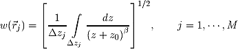 (13) (13)
for the inversion of surface data, where  =3.0 and =3.0 and  is used to identify the jth cell and is used to identify the jth cell and  zj is its thickness. This weighting function is first normalized so that the maximum value is unity. Numerical tests indicate that when this weighting is used, the susceptibility model constructed by minimizing a model objective function in eq.(8), subject to fitting the data, places the recovered anomaly at approximately the correct depth. zj is its thickness. This weighting function is first normalized so that the maximum value is unity. Numerical tests indicate that when this weighting is used, the susceptibility model constructed by minimizing a model objective function in eq.(8), subject to fitting the data, places the recovered anomaly at approximately the correct depth.
Note that if the data set involves highly variable observation heights the normal depth weighting function might not be most suitable. Distance weighting used for borehole data may be more appropriate - as explained next.
"Depth" weighting for borehole data
For data sets that contain borehole measurements, the sensitivities do not have a predominant decay direction, therefore a weighting function that varies in three dimensions is needed. We generalize the depth weighting used in surface data inversion to form such a 3D "depth" weighting function called distance weighting:
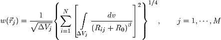 (14) (14)
where =3.0 and Vj is the volume of jth cell, Rij is the distance between a point in Vj and the ith observation, and R0 is a small constant used to ensure that the integral is well define (chosen to be a quarter of the smallest cell dimension). Similarly, this weighting function is normalized to have a maximum value of unity. For inversion of borehole data, it is necessary to use this more general weighting.
Note: This weighting function is also advantageous if surface data with highly variable observation heights are inverted.
The weighting function is directly incorporated in the sensitivity file generated by program MAGSEN3D. This program allows user to specify whether to use the depth weighting or the distance weighting for surface data. When borehole data are present, however, distance weighting must be used.
1.5 Wavelet Compression of Sensitivity Matrix
The two major obstacles to the solution of large scale magnetic inversion problem are the large amount of memory required for storing the sensitivity matrix and the CPU time required for the application of the sensitivity matrix to model vectors. The MAG3D program library overcomes these difficultie by forming a sparse representation of the sensitivity matrix using a wavelet transform based on compactly supported, orthonormal wavelets. For more details, the users are referred to Li and Oldenburg (1997). In the following, we give a brief description of the method necessary for the use of the MAG3D library.
Each row of the sensitivity matrix in a 3D magnetic inversion can be treated as a 3D image and a 3D wavelet transform can be applied to it. By the properties of the wavelet transform, most transform coefficient are nearly or identically zero. When the coefficient with small magnitude are discarded (the process of thresholding), the remaining coefficient still contain much of the necessary information to reconstruct the sensitivity accurately. These retained coefficients form a sparse representation of the sensitivity in the wavelet domain. The need to store only these large coefficients means that the memory requirement is reduced. Further, the multiplication of the sensitivity with a vector can be carried out by a sparse multiplication in the wavelet domain. This greatly reduces the CPU time. Since the matrix-vector multiplication constitutes the core computation of the inversion, the CPU time for the inverse solution is reduced accordingly. The use of this approach increases the size of solvable problems by nearly two orders of magnitude.
Let G be the sensitivity matrix, and  be the symbolic matrix-representation of the 3D wavelet transform. Then applying the transform to each row of G and forming a new matrix consisting of rows of transformed sensitivity is equivalent to the following operation, be the symbolic matrix-representation of the 3D wavelet transform. Then applying the transform to each row of G and forming a new matrix consisting of rows of transformed sensitivity is equivalent to the following operation,
 (15) (15)
where  is called the transformed matrix. The thresholding is applied to individual rows of by the following rule to form the sparse representation s, is called the transformed matrix. The thresholding is applied to individual rows of by the following rule to form the sparse representation s,
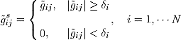 (16) (16)
where  i is the threshold level, and i is the threshold level, and  and sare the elements of and s, respectively. and sare the elements of and s, respectively.
The threshold level i are determined according to the allowable error of the reconstructed sensitivity, which is measured by the ratio of norm of the error in each row to the norm of that row, ri(i). It can be evaluated directly in the wavelet domain by the following expression:
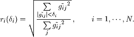 (17) (17)
Here the numerator is the norm of the discarded coefficients. For each row we choose i such that ri(i)=r*, where r* is the prescribed reconstruction accuracy. However, this is a costly process. Instead, we choose a representative row, i0, and calculate the threshold level i0 . This threshold is then used to define a relative threshold  . The absolute threshold level for each row is obtained by . The absolute threshold level for each row is obtained by
 (18) (18)
The program that implements this compression procedure is MAGSEN3D. The user is asked to specify the relative error r* and the program will determine the relative threshold level  . Usually a value of a few percent is appropriate for r*. When both surface and borehole data are present, two different relative threshold levels are calculated by choosing a representative row for surface data and another for borehole data. For experienced users, the program also allows the direct input of the relative threshold level . . Usually a value of a few percent is appropriate for r*. When both surface and borehole data are present, two different relative threshold levels are calculated by choosing a representative row for surface data and another for borehole data. For experienced users, the program also allows the direct input of the relative threshold level .
1.6 Choice of Tradeoff Parameter
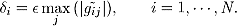
The choice of the tradeoff parameter ultimately depends upon the magnitude of the error associated with the data. The inversion of noisier data requires heavier regularization, thus a greater value of is required. In this section, we discuss the various implementations for the choice of in the MAG3D library.
If the standard deviation associated with each datum is known, then the data misfit define by eq.(10) has a known expected value  *, which is equal to the number of data when the errors are assumed to be independent Gaussian noise with zero mean. The value of should be such that the expected misfit is achieved. This entails a line search based on the misfit curve as a function of . Because of the positivity constraint, our problem is nonlinear. Thus for each a nonlinear solution using a logarithmic barrier method must be obtained. This is computationally demanding and we therefore have developed the following strategy to reduce the cost. *, which is equal to the number of data when the errors are assumed to be independent Gaussian noise with zero mean. The value of should be such that the expected misfit is achieved. This entails a line search based on the misfit curve as a function of . Because of the positivity constraint, our problem is nonlinear. Thus for each a nonlinear solution using a logarithmic barrier method must be obtained. This is computationally demanding and we therefore have developed the following strategy to reduce the cost.
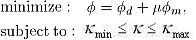
It is observed that, when plotted on a log-log scale, the misfit curves for 3D magnetic inversion with and without positivity often parallel each other in the vicinity of the expected misfit The curve with positivity must lie above the curve without positivity. Therefore, we can first perform a line search without positivity to find a 0 that gives rise to *. This search also generates the slope, s0, of misfit curve at 0. This process is very efficient and the required CPU time is much smaller compared to the time required for the solution with positivity. We next assume that s0 can be used to approximate the slope of the misfit curve when the positivity is imposed. A rigorous line search incorporating positivity starts with an initial guess of =0.50. This usually yields a misfit that is very close to the target value. If the misfit is not sufficientl close to *, however, a new guess for is obtained which makes use of the approximate slope s0. The inversion with updated can be solved efficientl if the logarithmic barrier algorithm is started from an initial model close to the fina solution. That model is obtained by perturbing the solution corresponding to the previous away from the zero bound. The line search using this strategy is often successful in reaching the target * after testing two to four values of . This strategy is implemented in MAGINV3D as the first method for choosing the tradeoff parameter.
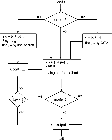 Figure 3 Figure 3. Flow chart illustrating the solution of the 3D magnetic inversion by MAGINV3D using different strategies for choosing the tradeoff parameter. |
In practical applications the estimate of data error is often not available. Then the degree of regularization, hence the value of needs to be determined based on other criteria. A commonly used method in linear inverse problems is the generalized cross-validation (GCV) technique. The use of GCV in inverse problems with inequality constraints such as positivity is far more involved and numerically expensive to implement. However, applying GCV on the 3D magnetic inversion without positivity still produces a reasonable estimate of the data error. That error can serve as a starting point for further adjustment by the user based on his or her judgement. Since no other information is assumed, we have chosen to use the value of obtained in this manner directly in the final inversion, which has the positivity imposed. In this case, only one logarithmic barrier solution is needed. Numerical tests have indicated that this simplistic use of GCV is in fact surprisingly effective unless the data have a large negative bias or are distributed sparsely. MAGINV3D has implemented this approach as the third method for choosing the tradeoff parameter.
Figure 3 illustrates the structure of the program MAGINV3D. It has three options for determining the tradeoff parameters. The controlling parameter is mode. When mode=1, the line search based on known target value of data misfit is used. Two stages, as discussed above, are used and several solutions for different values of must be tested to obtain one that produces the target misfit. When mode=2, the user specifie a tradeoff parameter and a single solution is produced. When mode=3, the program first performs GCV analysis on the inversion without positivity and then uses the resultant value of in the final inversion.
1.7 Example of Inversion
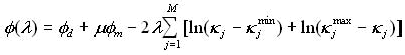
We now invert the total field anomaly data in Figure 2 using program MAGINV3D. The model region is discretized into 24 by 24 by 16 cells. The cells are all cubes of 25 m on a side. A total of 344 data (175 surface data and 144 three-component borehole data) are inverted to recover the susceptibility in 9,216 cells.
For a model objective function, we choose s=0.0001, X=Y=Z=1.0, and a distance weighting with R0=6.2 m. A zero reference model is used. Figure 4 shows one cross-section and one plan-section of the recovered
model. The two target prisms are well define in both horizontal and vertical locations and their amplitudes are comparable to those of the true model.
 |
Figure 4. The susceptibility model recovered from the joint inversion of total-field surface data and three-component borehole data. The distance weighting function is used in this inversion. This model clearly define both prisms and whose true positions are indicated by the solid white lines. |
1.8 References
Bhattacharyya, B. K., 1964, Magnetic anomalies due to prism-shaped bodies with arbitrary magnetization: Geophysics, 29, 517-531.
Li, Y. and Oldenburg, D. W., 1996, 3–D inversion of magnetic data, Geophysics, 61, 394–408.
Li, Y. and Oldenburg, D. W., 2000, Joint inversion of surface and three-component borehole magnetic data, Geophysics, 65, pp540-552. .
Li, Y. and Oldenburg, D. W., 1997, Fast inversion of large scale magnetic data using wavelets, 67th Ann. Internat. Mtg., Soc. Expl. Geophys., Expanded Abstracts, 490–493.
Sharma, P. V., 1966, Rapid computation of magnetic anomalies and demagnetization effects caused by bodies of arbitrary shape: Pure Appl. Geophys., 64, 89–109.
|
