| |
Introduction
NOTES:
- Back to the instructions and explanations page.
- The questions on this page are to be answered if the exercise was assigned by an instructor. Sections are the same as those in the instructions, and you should be able to answer questions AFTER carrying out work for each corresponding section.
Steps 1 and 2 - Setup and Physical Properties
- What geologic materials are expected in this investigation? For our example, there should be at least three.
- What range of values do you expect for the relevant physical property(ies) of these materials, at this site? For example, which material will have the highest value, which will have the lowest value, etc.
- What do you expect for depths and dimensions for the features and targets of this scenario? In our case, this means depth and extent of overburden, and the likely width and depth of the trench.
- Are there any aspects of the field site that may cause responses that are not related to the target questions?
- Why was it difficult to carry out further DC resistivity measurements south of position 26m?
Steps 3 and 4, surveys and data
- Based upon the site sketch and the survey configuration, how would you label the x-axis of the two line profile plots (figures 3 and 4)?
- Does the simple profile recorded using n=1 reveal anything related to our task? Even some indication about changes in materials can be useful.
- Similarly, does the simple profile recorded using n=3 reveal anything related to our task?
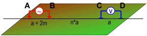
Figure 2: a generic dipole-dipole survey electrode arrangement. |
Questions related to the complete raw data, viewed as a pseudosection. Recall that the objective of inspecting raw data is to gain some feeling for what information the data might contain, and for data quality.
- Which rows of data points on this pseudosection represent the data gathered with a distance B-C of 6m (see Figure 2)?
- Under which segment of this survey line does there appear to be resistive overburden?
- Describe any evidence of the trench on this raw resistivity data set.
- Find out the positions of the two electrodes that were used to measure the potential of the "deepest", right-most data value. Identify these two electrodes by their line positions. (Recall that clicking on a data point pops up a dialogue box with datum details, and displays the electrode positions involved in acquiring that data point.)
- Having seen the apparent resistivities that were measured, what do you think the true resistivities will be for overburden, trench and surrounding materials?
- Are there any data points that appear to be outliers? In other words, are there any apparently "bad" measurements?
Steps 5: Processing (in this case, 2D inversion)
Assessing the first inversion result
- From the log file,
- list the following parameters: The total CPU processing time, total number of iterations performed, the “exit” message in the inversion log file, the value of target misfit and the value of achieved misfit.
- In units of Ohm-m, what was the reference model the program chose to use? It is given as conductivity in the log file.
-
SIDEBAR: Saving images from programs
To save images of data or models you must click the “copy” button on the tool bar (the second button), then go to an open document (MS Word, WordPad, etc.) move the cursor to where you want the image to appear, the press CTRL-V to paste the image into the document. Then resize as desired. It is very important to add captions to each image included in work that you deliver. |
From observed and predicted data:
- First paste a copy of the data and the difference map into your answer document. See the sidebar "Saving images from programs".
- Identify which two data points the program had the most difficulty re-creating. Either circle and label them on the image, or list the coordinates of their four electrodes.
- We don't want to over-interpret our first result. Other possible models must be produced, however, first impressions about the information revealed by inversion are worth considering:
- Paste a copy of the model image with it's convergence curves into your answer document and include a caption.
- What are the smallest and largest resistivities recovered by this first model.
- How many cells are there that appear to have the largest resistivity?
- Change the colour bar's Min / Max (Options menu) so the max is half what it was to begin with. How does this change your impression of the geology?
- Observe the convergence graphs.
- What was the value of the target misfit? "Misfit" is a number quantifying the difference between measurements and predicted data. It is used by the algorithm to help decide how to progress.
- Compare this target misfit value to the value of ( Chifact )*( number of data values ).
- At what iteration was the desired misfit attained (blue curve)?
- How many additional iterations were required before the program completed the inversion?
- Was the program able to reduce the value of the model norm during it’s last few iterations (red curve).
At each iteration the "model norm" is a number that quantifies both how smooth the model is, and how close it is to a reference. It is used by the algorithm to help decide how to progress.
Second inversion
- Did this inversion run converge? If not, ask the instructor for help. You should have a ligitimate second inversion model.
- What one significant noticable difference between this model and your first model? You can think in terms of values, or locations & shapes of features.
- Identify and describe two significant similarities between this model and your first model?
Using two models
- The image showing the model with so-called "depth of investigation" cutoff should be in your answer document with a caption.
- Explain in 1 or 2 sentences how to think about the "hatched region" of this figure.
Tightening misfit
No specific questions here - continue with the final step.
Step 7: Synthesis
- Identify two differences between the model obtained by "tightening misfit" and your previous results.
- Based upon your inversion results:
- Identify probable ranges of values for the three geologic materials you expected to find at this site. (NOTE: you can see exact values of resistivity in each cell by clicking your mouse's left button while pointing to the cell in the model display window. The X-position, Z-position, and value under the mouse pointer is displayed in the window's status bar (at the bottom).)
- Compare these values with the estimates you made above directly from apparent resistivities of the raw data pseudosection.
- What is your estimate for depth of overburden between positions 0 and 13 metres?
- What is your estimate for the (i) location, (ii) width and (iii) depth to the bottom of the buried trench?
- Describe one reason that estimating this depth of the trench a little tricky.
- Under what line position (in the site sketch) is target the target centred.
- How far into the ground do you feel that information is reliable in the vicinity of the trench? In other words, what is your estimated depth of investigation in the zone of interest?
- Describe briefly any other aspects of your model of the earth that have not yet been mentioned, but which you think might be of interest to the engineers in charge of making use of this information. Are there any surprises? Any difficulties or confusing aspects?
- Provide two examples of how three models provided more or better information than if only one model had been used.
- Describe at least one shortcomming of the model as it is presented. In other words, try to anticipate at least one "complaint" that an engineeer might make about these results if he/she has never encountered this kind of geophysical information before.
|
|
