| |
Related documentation:
| DCIP2D user interface | data viewer | model maker | model viewer | tutorial |
 This program controls all aspects of inverse processing and interpretation. Note that it is very important to save work associated with each inversion in separate directories. See the first item under Tool bar functions. DC data must be inverted first, then results are used during inversion of IP data. See the last item under Tool bar functions. This program controls all aspects of inverse processing and interpretation. Note that it is very important to save work associated with each inversion in separate directories. See the first item under Tool bar functions. DC data must be inverted first, then results are used during inversion of IP data. See the last item under Tool bar functions.
DCIP2D capabilities and limitations
Array types:
All linear survey surface-array types, including non-standard or un-even arrays, can be inverted. The only limitation is that teh mesh must be designed so that electrodes are on mesh nodes. This must be remembered if horizontal distances are not regular, such as when line positions were not corrected for topography.
The GUI was designed with our sponsoring companies in mind, and they are mining exploration firms. Therefore the user interface works well with dipole-dipole, pole-pole, pole-dipole, and Wenner or RealSection arrays. Schlumberger, gradient, and other arrays can all be inverted but unfortunately the user interface does not yet handle those types of arrays. As of Dec 2005, Realsection and Wenner arrays can be viewed in dcip2d-data-viewer (see data viewer manual).
Working with arrays other than dipole-dipole and pole-dipole
To work with Wenner, Schlumberger and other arrays, build the input files as per the manual, but specify dipole-dipole on the second line of the observations file. You must also define your own mesh, and enter reasonable inversion control parameters in the user interface. This interface estimates default parameters properly ONLY for dipole-dipole, pole-pole and pole-dipole arrays. Finally, the pseudosection display will not appear properly for Wenner or Schlumberger arrays. However the inversion will run fine, and the resulting model can be viewed normally with the user interface.
Mesh design
The electrodes need to be on node positions, and good results are usually obtained when there are two mesh cells between each station, and cell thickness is half it's width. Don't forget to add padding cells on all three sides around the region where current was injected.
Menu
The menu functions are either common to all Windows95 programs, or are duplicated by tool bar buttons.
Tool bar functions
Button functions are described on the status line at the bottom of the window when the mouse pointer is held over a button.
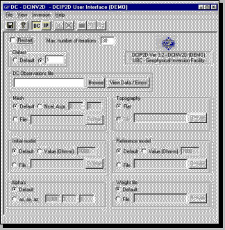
- You can not run an inversion until an input file has been opened, and changes to parameters have been saved. For each new inversion that must be kept, create a separate directory (in the save dialogue) so that previous results are not overwritten by the current processing run.
- The model, predicted data, and log file buttons are not active until at least one iteration of an inversion has been completed because they all require output from the inversion program.
- Pressing the model button opens the Model Display window, described later.
- Pressing the pre button opens the Data Viewing window with observed and predicted pseudosections, also described later.
- Pressing the log file button displays the inversion program's log file in a NoteBook window. In NoteBook, press CTRL-End to see convergence specifications in the last few lines. The rest of the information is not useful to the average user.
- Pressing the IP button opens a window for setting up inversion of induced polarization data. The window is similar to the DC inversion control window, except there is an additional field for specifying the required conductivity model. A DC inversion must be completed before IP data can be inverted.
Parameters
Dialogue sections of the window are used for all the necessary inversion algorithm parameters.
- Restart: This check box is usually left blank. If it is checked, an inversion that did not finish, or did not converge, can be continued without starting from scratch.
- Number of iterations: Inversion processing will stop after this many iterations regardless of whether convergence was reached.
- Chifact: Specifies the final target misfit. Recall that target misfit "should" be N. The actual target misfit used by the program will be chifact × N. If the Default button is clicked, the misfit criterion is chosen based on convergence behaviour. A large number of iterations may be required.
- Observations: Specifies the input data file.
- This input file contains potentials (normalized by source current), and the locations of all electrodes for each measurement. It can specify the error assigned for each datum, but errors can also be automatically assigned.
- The browse button helps specify which data file to use.
- Inspect data using the View Data / Errors button. This window includes options for viewing, adjusting, and copying the raw data pseudosection. Global or individual datum errors can also be assigned (details are below). The pre and diff options are active only after an inversion has been run.
- Mesh: The subsurface is modelled as a mesh of cells.
- Default tells the program to build it's own mesh based on the positions of data. This is usually the best option.
- Specifying (Ncel, Aspr) builds a mesh with Ncel cells per datum (horizontally), and Aspr for each cells's aspect ratio. Padding cells are added outside the region of the survey.
- A mesh definition file can also be specified.
- Topography: If there is a file detailing topography along the survey line, specify it here.
- Initial model: This is an earth model that gets the inversion started.
- It is usually a uniform halfspace. The default is a model identical to the reference model.
- When working with many adjacent survey lines it may be useful to use results from one inversion to start the inversion of the subsequent line.
- Reference model: Model characteristics are specified in relation to a reference. For example, a "small" model means one that is similar to a reference model. The default reference model is a uniform halfspace with constant conductivity based on the data (by default).
- Alphas: These three values specify what type of model the inversion will look for.
- Recall that length scales should help determine the values of alpha parameters. If the scales of interest are Lx and Lz, then alpha parameters should be set to satisfy
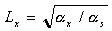 and and  , where , where
- (total width of mesh) < Lx < (mesh cell width)
- (total depth of mesh) < Lz < (mesh cell thickness)
- For example (s, x, z) = (0.001, 1, 1) specifies a model that will be smooth in both vertical and horizontal directions, but not necessarily very close to the reference model (relatively small s).
- (s, x, z) = (1, 0.001, 0.001) specifies a model that will be small (i.e. as similar to the reference as possible), but not necessarily smooth in either direction.
- Weight file: Specifies a file that helps demand a model with specific characteristics. We will not use this feature, but it allows you to incorporate prior knowledge about the geology.
|
|
