 |
2D model maker for DCIP2D forward modelling |
|
Related documentation: This page outlines how to use the program dcip2d-model-maker for building 2d resistivity and chargeability models in the UBC-GIF rectangular mesh format. InstallationThe following programs are required to build 2D models, run a forward calculation and view the result as a pseudosection. Inversion is not discussed in this document.
NOTE REGARDING SAVING WORK:
|
|||||||||||||||||||

|

|
Before running a forward calculation your model must be discretized onto a mesh using the UBC-GIF format. This is a very important step and the result of discretizing the model you have defined will significantly affect the data that result from running a forward calculation. This calculation is performed on a discrete model, so you must be sure you are satisfied with the way the program has converted your subsurface model into the discrete domain. Carry out the discretization by clicking the mesh button ![]() . If you have not already saved your model you will be reminded at this point. You are permitted to specify the name of the model to be saved. See the note regarding saving to new directories above.
. If you have not already saved your model you will be reminded at this point. You are permitted to specify the name of the model to be saved. See the note regarding saving to new directories above.
Parameters in the "Discretize Model" dialogue should be self explanatory, except that the "aspect ratio" means the ratio of width to depth of the cells in the top few layers. An aspect ratio of 2:1 is normal for these top few rows, with aspect ratio reduced to 1:1 for the padding cells below the region of interest. Note that it is not recommended to request fewer than 2 cells per electrode, but more may help produce smoother results. Of course, more cells will result in lengthier calculations.
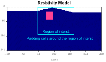
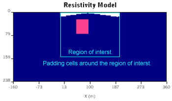
Upon accepting the discretization parameters, the model that will be used for forward calculations is displayed in a separate model display window. Also, the discretization, as well as a sketch of the survey geometry, is overlaid on the model in the modelling window. For the model that will be used in forward calculations, the region of interest will be augmented with "padding cells" which are required to ensure that boundary conditions at the edges of the domain modelled by inversion are well controlled. For example, the two figures in the section on topography above show how a region of interest ranging from (x1, x2) = (0, 200), with depth extent of 100 is augmented to include padding cells to the left, right, and underneath of the region of interest.
Using the model display window (which is the same as that used to display inversion results), observe how your buried blocks and topography have been converted to rectangular cells. Use the mesh-view button in the model viewing window to see how the mesh has been imposed upon the subsurface features. There are more instructions on using dcip2d-model-viewer in a separate help file. If the discretization you see is not suitable, go back to the modelling window and adjust the model. Otherwise you are ready to perform the forward calculations. (The model display can be invoked anytime there is a model available by clicking the ![]() button.)
button.)
Wenner and Schlumberger arrays are not included in the electrode geometries. These can be simulated by generating a pole-pole data set, then working with the resulting data file to generate data that would arise from a different survey configuration by subtraction of appropriate pairs of pole-pole data. Recall that the research priority at the UBC-GIF is inversion theory and methodology, and graphical user interface programs that accompany forward and inversion codes are constructed to support research rather than to satisfy the needs of third parties.
Once you are satisfied with the discretization that has been applied you are ready to perform a forward calculation. Click the forward modelling button ![]() . A command line ("DOS") window will appear to indicate progress of the calculation.
. A command line ("DOS") window will appear to indicate progress of the calculation.
When the forward calculation is finished, the command line window will disappear, you can examine the resulting data as a pseudosection by clicking the ![]() button. Details on using dcip2d-data-viewer are provided in a separate document.
button. Details on using dcip2d-data-viewer are provided in a separate document.
So far we have only worked with resistivity models. By clicking the "IP" button, you can add subsurface blocks representing variations in chargeability. Notice that the resistivity structures are outlined in dashed lines while working in the chargeability mode. Forward modelling of chargeability data is performed using the same sequence of steps as for resistivity, but you must be in the IP mode (with the "IP" button down) throughout.
 Currently, the program can work only with theoretical dimensionless intrinsic chargeability, so values must be between 0.0 and 1.0. See the UBC-GIF website (http://www.eos.ubc.ca/research/ubcgif/documentation/dcipdocs/intro.html) for details of this definition for chargeability. To understand why these non-dimensional units are used, it should be recalled that inthe development of the IP inversion algorithms, the assumption was made that the IP response is the apparent chargeability obtained from an idealized time domain experiment. Using the figure to the right, the apparent cheargeability is defined as the ratio of the secondary potential
 ![]() s to the total potential measured
s to the total potential measured ![]() n which was measured just before the current is cut off. This is a dimensionless number and usually has a range of 0 to 0.5. In reality
n which was measured just before the current is cut off. This is a dimensionless number and usually has a range of 0 to 0.5. In reality ![]() s and
s and ![]() n are not generally recorded directly with the field acquisition system. In order to use UBC-GIF programs so that the output is a true "chargeability" defined by Siegel, 1959, it is necessary to convert collected IP data into the form assumed by these algorithms. An approximate conversion can be performed using the following approximate rules of thumb:
n are not generally recorded directly with the field acquisition system. In order to use UBC-GIF programs so that the output is a true "chargeability" defined by Siegel, 1959, it is necessary to convert collected IP data into the form assumed by these algorithms. An approximate conversion can be performed using the following approximate rules of thumb:
NOTE: The resistivity model should be correct before IP forward calculations are performed. You can adjust the resistivity model by clicking the "DC" mode button - then the chargeability blocks are outlined in dashed lines.